|
ГЛАВНАЯ
> Вернуться к содержанию
Cybernetics and programming
Правильная ссылка на статью:
Lobanov A.A.
Conceptual optical schemes of direction finding computational devices for guiding the space probe to a landing point on small bodies of the solar system
// Кибернетика и программирование.
2019. № 1.
С. 83-89.
DOI: 10.25136/2644-5522.2019.1.28720 URL: https://nbpublish.com/library_read_article.php?id=28720
Conceptual optical schemes of direction finding computational devices for guiding the space probe to a landing point on small bodies of the solar system /
Концептуальные оптические схемы пеленгационных вычислительных устройств для наведения космического зонда на точку посадки на малых телах Солнечной системы
Лобанов Александр Анатольевич
кандидат технических наук
доцент, кафедра инструментального и прикладного программного обеспечения, МИРЭА – Российский технологический университет
119454, Россия, г. Москва, пр. Вернадского, 78, каб. Г-225
Lobanov Aleksandr Anatolevich
PhD in Technical Science
Associate Professor, Department of Instrumental and Applied Software, MIREA Russian Technological University
119454, Russia, g. Moscow, pr. Vernadskogo, 78, kab. G-225

|
aa.lobanoff@ya.ru
|
|
 |
Другие публикации этого автора
|
|
|
DOI: 10.25136/2644-5522.2019.1.28720
Дата направления статьи в редакцию:
21-01-2019
Дата публикации:
04-03-2019
Аннотация:
Объектом исследования является методология построения оптических корреляционных устройств, предназначенных для решения задачи пеленгации в целях автономного наведения космических летательных аппаратов. Предметом исследования является возможность выполнения преобразования Фурье оптическими устройствами. В статье рассматриваются особенности принципиальных моделей оптических вычислительных устройств для построения корреляционной характеристики и создания корреляционно-экстремальной системы наведения и посадки космического аппарата. Выполнено исследование общих свойств и принципов функционирования оптических вычислительных устройств. Рассматриваются вопросы разработки научных методов и алгоритмов оптической обработки визуальных пространственных данных. Описан перспективный подход к созданию пеленгационного вычислительного устройства на основе Фурье преобразования, выполняемого оптической системой, для определения угловых координат интересующего объекта. В настоящем исследовании используется методы структурного и математического моделирования для создания и анализа моделей, описываемых оптических вычислительных корреляционных устройств. На основе выполненного анализа моделей оптических корреляционных вычислительных устройств описаны преимущества и недостатки существующих оптических схем. Результатом данного анализа стало выдвижение формальных требования к специальному бортовому оптическому вычислительному устройству для наведения космического летательного аппарата на точку посадки на малом теле Солнечной системы. Перспективность создания подобного оптического вычислительного устройства обусловлена снижением нагрузки на аппаратную часть бортового вычислительного комплекса космического летательного аппарата.
Ключевые слова:
оптическая обработка, распознование изображений, бортовой вычислительный комплекс, автономное наведение, оптический вычислитель, пространственная информация, оптическая схема, пеленгация, автономная навигация, пространсвенные данные
Abstract: The subject of the research is an optical direction finder for the navigation and guiding a space probe. The usage of the optical correlation computing device is determined by the necessity to reduce the load to a space probe on-board computer system. The paper describes especially the optical correlation computing devices for building the correlation-extremal direction finders. The principle optical schemes of this class of optical devices are described. The method of mathematical modeling is used for building and analyzing the optical scheme of the proposed optical correlation computing devices. Both advantages and disadvantages of the existed optical schemes are noted. The requirements to parameters of the special on-board optical correlation computing device for the direction finding are proposed. It is shown that the optical device potentially can be used for navigation and guiding a space probe in the process of the landing on a small body of the solar system.
Keywords: optical processing, image recognition, on-board computing system, autonomous guidance, optical computer, spatial information, optical scheme, direction finding, autonomous navigation, spatial data
Introduction
We assume that special navigation and guiding system is necessary for the precise soft landing a space probe on small bodies of the solar system. The main part of this system is a direction finder. Currently, optoelectronic tracking systems are widely used for the purposes of direction finding. These systems use the correlation analysis for support of the direction finding. This method requires a relatively small number of object’s elements for the direction finding [1-7] The performance of CE-system depends on the on-board electronic hardware. The on-board equipment is significantly less power than ground based analogs because of the demand of vibration, temperature and radiation resistance [8-10]. Thus it is very important to choose an optimal algorithm that is not overload on-board hardware.
In this paper is described an alternative approach for the navigation and guiding CE-system. It is possible to create CE-systems with correlation in the optical path [11-15]. That optical (versus electronic) CE navigation and guidance systems are characterized by the high speed and significantly lower requirements to the hardware of the on-board computing system. This paper describes the possible options for the construction of the space probe CE navigation and guidance systems based on the correlation in the optical path.
The variation of the optical elements in the system allows to build the system performs various types of mathematical operations (e.g. addition, multiplication, differentiation, integral convolution, mutual correlation, Fourier transform etc.) [11,12,16-20]. The ability of the optical systems to implement Fourier transform [8,9] could be used to build an optical direction finder with high performance [11-15].
Optical computing devices have at least three essential advantages over electronic devices with similar functions [8,9]. The first one is that the of optical direction finders are real time simultaneous two-dimensional spatial information processing complexes. Electronic CE-systems implements separate transform of a spatial information by the X coordinate and by the Y coordinate. That procedure demands more resources or could be implemented step by step. In the last case we lose real time procedure. The second is that, in optical computing devices the speed of transform does not depend on the complexity of the processed function or algorithm. The time of implementation in optical computing devices depends on the speed of the light propagation in the optical system. It implements the transform practically instant. The third advantage of the optical computing devices is a relevant simplicity of the construction, small size and light weight. All these advantages of the optical computing devices are very important for building a CE-system for navigation and guiding the space probe during its landing on the small bodies of the solar system.
Formal description of the optical correlator finder scheme
The optical CE-system implements the mutual correlation of two functions g and h. Where g and h are functions of the coordinates x, y. Functions g and h also depend on the point of origin shift. The functions g and h could be defined by the following expression [18]:

where h* – is the complex conjugate of the function h.
If the functions are identical (g(x, у) = h(х, у)), we can define (1) as follows:

The integral operation (2) is called autocorrelation function.
It is proved [15] that the module of the autocorrelation function (real or complex) has an absolute maximum at u=0, v=0:

The relation (3) allows to determine the coordinates of the shift (u,v) if we know the position of the maximum of the correlation function. The position of the maximum could be used to build the direction finding characteristics. Optical computing devices which can implement the operation of mutual correlation of two functions are called optical correlators. That class of CE-systems could be used as a part of onboard computing complex for navigation and guiding a space probe during the dissent and landing on the surface of a small body of the solar system.
It is possible to build the optical direction finder using one of two types of optical schemes. The first type is based on the coherent illumination. The coherent type is difficult to use for landing a space probe. The second type uses incoherent illumination. The principle of operation incoherent optical computing systems is based on the application of the laws of geometric optics [20]. Figure 1 presents a scheme of the incoherent optical correlator [9,18,21], which consists of two thin collecting components (lenses). The main points H1, H1', и H2, H2' are jointed.
A radiation receiver is located in the rear focal plane of the second component (analysis plane), which is optically coupled to the plane of the radiation source. The first component acts as a collimator and creates parallel beams passing through the transparencies. The second component collects in its rear focal plane the energy of optical radiation transmitted through the transparencies, i.e. performs the integration operation.
The concept of the optical computer processing is based on the fundamental of a light tube. An optical radiation energy propagation could be described as a physical light beam. It is possible to formalize a physical light beam as an elementary light tube. The light tube as a physical phenomenon is the tube that has a diameter (transverse dimensions) is infinitely small compared to its length [20]. The direction of propagation is the axis of the light tube. The wave of a light energy propagates along the axis of the light tube.
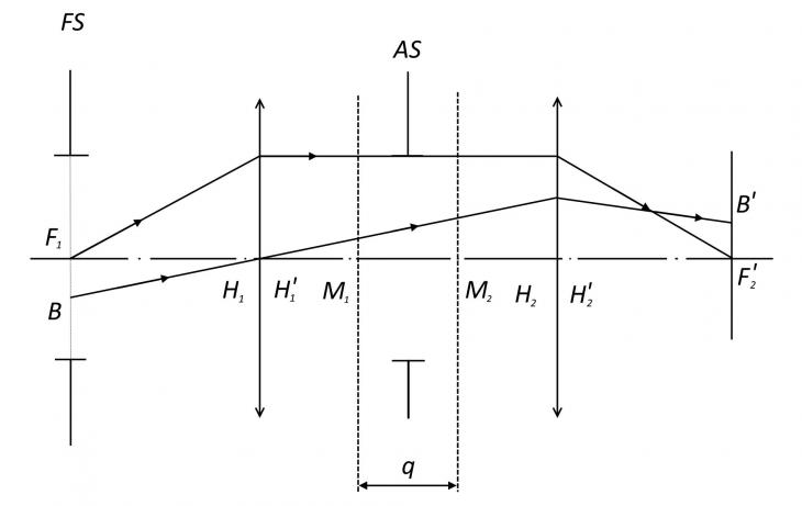
Figure 1–The scheme of incoherent optical correlator
Let us select an arbitrary off-axis point B in the plane of the radiation source and let the beam pass through the combined main points from it Н1 и Н1' at some angle to the optical axis (figure 1), Passing through the first component without refraction, the beam will cross the plane of the first transparency at point М1 with coordinates (x, y), and the plane of the second transparency at point М2 with coordinates (x+u, y+u) (the origin of the coordinate system can be chosen arbitrarily, but the axis OZ must coincide with the optical axis). After refraction on the second component, this beam will pass through the point В', conjugated to the point B.
Now let’s consider an elementary light tube, the axis of which is the specified beam. The radiation flux Ф0, going inside the light tube from the elementary site centered at point B, will be weakened when passing through the lens components and transparencies. Assuming that the transmittance of the lens components t0 is constant for all passing rays, we find the value of the radiation flux transferred by the physical beam to the analysis plane (4):

A physical integration is implemented in the reference area of the standard (АS). The area is limited by its light zone (diameter of the first optical element), and depending on the size of the aperture and the distance between the first optical element and a transparency standard q.
The expression (5) presents a two-dimensional convolution of the function τ1 and τ2. Therefore, the presented optical system allows to implement the function of mutual correlation of the investigated and referencing images.
The spatial resolution of the system is limited by the diffraction. Diffraction significantly increases at a large size of aperture AS. Theoretically it is possible to decrease the by the reducing the distance between the transparency standard and first optical element of the system. Practically that decision is not always possible for constructive reasons. This problem is eliminated in the scheme shown in figure 2.
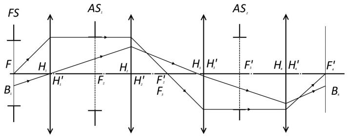
Figure 2 – a modified scheme of the incoherent optical correlator.
Where FS – a field stop of the system; ASi – an aperture stops of the system; Fi and F’i – main points of the thin components of the optical system; Hi and H’i – main plains of the system; B1 – an off-axis ray of the object; B4 – an image of the off-axis ray of the object in the image plane.
The optical system consists of four thin components (elements), the First and fourth elements perform the same functions as the elements in the previous scheme (see figure 1). The rear focal plane of the second element coincides with the front focal plane of the third element, and the analysis plane (the rear focal plane of the fourth element) will be optically conjugated with the plane of the source of incoherent radiation (the front focal plane of the first element). The optical standard (reference image) is located in the front focal plane of the second element that is corresponded in position with the rear focal plane of the third element. The plane of the test image and the plane of the reference images are optically conjugated. That solution allows to reduce the distance between the test image the reference image in the real system almost equal to zero (q=0). Aperture stop is a frame of the transparency standard (reference image) (see. figure 1). The advantages of the this scheme is the possibility of changing the scale of the studied and reference images, depending on the ratio of the focal lengths of the second and third elements. In particular, at the same focal lengths of the second and third components F2' и F3' the scales of the studied and reference images will be equal. However, the longitudinal dimensions of the optical system in the second case (figure 2) are much larger than in the first case (figure 1).
The presented optical systems of incoherent correlators (CE-systems) allow processing only unipolar signals. However, it is possible to introduce a constant component into the optical scheme and change the sign of the signal. The last method produces significant background signal would be registered by the radiation receiver. The problem is that the background signal usually exceeds the useful signal. The first part of the problem decision is the movement (transfer) the radiation receiver in the analysis plane. The second part of the solution to eliminate the background signal must be provided the mutual movement of the test and reference images [18]. The movement of the images demands (requires) some technical solution that performs these movements. A significant drawback of the previously described schemes is the need to use several similar devices (for example, three or four) to create a direction finding characteristic and a control signal [22, 23].
To obtain a multichannel CE-characteristic for navigation and guiding a space probe on the landing site at a surface of the small body of the solar system the optical direction finder has to: 1) consist of several optical correlators; 2) the Radiant flux should be proportional to the area of correlation (object image) and transmission of the standard recorded by the radiation receiver; 3) to reduce the effect of uneven sensitive areas of the radiation receiver, it is necessary that the illumination of the exit pupil of the direction finder over its entire area is uniform; 4) to fulfill this condition, the optical system of the direction finder must be free of vignetting.
Results
Two conceptual schemes of optical correlators which can be used for building the optical direction finder for navigation and guiding of a space probe are proposed. The usage of the optical direction finder is determined by the necessity to reduce the load to the on-board computer complex of a space probe. The combination of several optical correlators allows to determine the angular position of the landing site on a small body of the solar system. The optical direction finder mathematical model is built. This model is used for analysis of the proposed optical correlators. Both advantages and disadvantages of the optical schemes are discussed. It is shown that the optical device potentially capable to guide a space probe to the landing point on a small body of the solar system. We assume that, the proposed schemes of the optical correlator have a number of significant advantages. The usage of direction finders build on the scheme of the proposed correlator reduces the resource requirements to the onboard computer complex, which is important for the creation of on-board autonomous guiding and navigation system of the space probe. The solid construction of the optical computing device and the relevant simplicity of the design increase the reliability of the on-board computing complex. The requirements to the parameters of the prospective optical correlation direction-finder are determined.
Библиография
1. T. Kubota, et al, An autonomous navigation and guidance system for MUSES-C asteroid landing, Acta Astronautica, 52(2-6): 125–131, 2003.
2. C. Cocaud and T. Kubota, Autonomous navigation near asteroids based on visual SLAM," in Proceedings of the 23rd International Symposium on Space Flight Dynamics, Pasadena, California, 2012.
3. S. Kulumani, K. Takami, T. Lee, Geometric control for autonomous landing on asteroid Itokawa using visual localization, in Proceedings of the AAS Astrodynamics Specialist Conference Stevenson, WA, 2017.
4. T. Miso, T. Hashimoto, and K. Ninomiya, Optical guidance for autonomous landing of spacecraft," IEEE Transactions on Aerospace and Electronic Systems, vol. 35, no. 2, pp. 459{473, 1999, issn: 0018-9251. doi: 10.1109/7.766929.
5. Cheng Y., Johnson A., Matthies L., "MER-DIMES: a planetary landing application of computer vision", IEEE Comp. Soc. Int. Conf. on Computer Vision and Pattern Recognition, San Diego, USA, 2005.
6. Johnson A., Ansar A., Matthies L., Trawny N., Mourikis A.I., Roumeliotis S. I., "A General Approach to Terrain Relative Navigation for Planetary Landing," AIAA Infotech at Aerospace Conference, Rohnert Park, USA, 2007.
7. Cocaud C., Kubota T., “SLAM visual landmark 3D mapping system for autonomous navigation and landing on small celestial bodies”, 35th Annual American Astronomical Society (AAS)-Guidance and Control Conference, Breckenridge, USA, 2012.
8. Якушенков, Ю.Г. Проектирование оптико-электронных приборов. / Ю.Г. Якушенков 2-е изд. — М.: Логос, 2000. — 489 с.
9. Акаев, А.А. Оптические методы обработки информации / А.А. Акаев, С.А. Майоров – М.: Высшая школа, 1988, 237 с.
10. Сырямкин В.И. Корреляционно-экстремальные радионавигационные системы / В.И. Сырямкин, В.С. Шидловский Томск: Изд-во Том. ун-та, 2010. – 316 с.
11. Боголюбов И.А., Лобанов А.А., Филонов А.С. Применение оптического пеленгатора для целей посадки космического летательного аппарата на малые тела солнечной системы // Научный альманах. – 2017. №5-3(31). – С. 45-48.
12. Лобанов А.А., Филонов А.С. Метод оптической обработки пространственной информации для целей наведения и посадки космических летательных аппаратов на малые тела солнечной системы. // Кибернетика и программирование. – 2018. – № 2. – С.94-102
13. Лобанов А.А., Мордвинов В.А., Мураков М.В., Раев В.К. Построение модели многофункционального бортового комплекса наведения и посадки КЛА // Программные системы и вычислительные методы. — 2018.-№ 2.-С.36-50. DOI: 10.7256/2454-0714.2018.2.26217. URL: http://e-notabene.ru/ppsvm/article_26217.html.
14. Гудмен Дж. Введение в Фурье-оптику: Пер. с англ. – М.: Мир, 1970, 364 с.
15. Богатырева В.В. Оптические методы обработки информации : учебное пособие / В.В. Богатырева, Л.А. Дмитриев – СПб.: СПбГУИТМО 2009, 74 с.
16. Сороко Л.М. Основы голографии и когерентной оптики. / Л.М. Сороко – М.: Наука, 1971. 616 с.
17. Оптическая обработка информации: Пер. с англ, /Под. ред. Д. Кейсесента.-М.: Мир, 1980, 237 с.
18. Зверев В.А. Оптические анализаторы. / В.А. Зверев, В.Ф. Орлов – М.: Советское радио, 1971, 240 с.
19. Розенфельд А. Обработка оптических изображений / А Розенфельд – Пер. с англ. М.: Мир, 1972, 232 с.
20. Слюсарев Г.Г. Геометрическая оптика. / Г.Г. Слюсарев – Л.: АН СССР, 1946, 332 с.
21. Белоглазов И.Н. Корреляционно-экстремальные системы. / И.Н. Белоглазов, В.П. Тарасенко – М.: Советское радио, 1974, 392 с.
22. Геча В.Я., Жиленев М.Ю., Федоров В.Б., Хрычев Д.А., Худак Ю.И., Шатина А.В. Скорость движения изображения при оптико-электронной съемке поверхности планеты // Российский технологический журнал. — 2018.-№ 4 (24). – С.65-77.
23. Лобанов А.А. Пространственный мониторинг // Славянский форум. — 2015.-№1 (7). – 128-136
References
1. T. Kubota, et al, An autonomous navigation and guidance system for MUSES-C asteroid landing, Acta Astronautica, 52(2-6): 125–131, 2003.
2. C. Cocaud and T. Kubota, Autonomous navigation near asteroids based on visual SLAM," in Proceedings of the 23rd International Symposium on Space Flight Dynamics, Pasadena, California, 2012.
3. S. Kulumani, K. Takami, T. Lee, Geometric control for autonomous landing on asteroid Itokawa using visual localization, in Proceedings of the AAS Astrodynamics Specialist Conference Stevenson, WA, 2017.
4. T. Miso, T. Hashimoto, and K. Ninomiya, Optical guidance for autonomous landing of spacecraft," IEEE Transactions on Aerospace and Electronic Systems, vol. 35, no. 2, pp. 459{473, 1999, issn: 0018-9251. doi: 10.1109/7.766929.
5. Cheng Y., Johnson A., Matthies L., "MER-DIMES: a planetary landing application of computer vision", IEEE Comp. Soc. Int. Conf. on Computer Vision and Pattern Recognition, San Diego, USA, 2005.
6. Johnson A., Ansar A., Matthies L., Trawny N., Mourikis A.I., Roumeliotis S. I., "A General Approach to Terrain Relative Navigation for Planetary Landing," AIAA Infotech at Aerospace Conference, Rohnert Park, USA, 2007.
7. Cocaud C., Kubota T., “SLAM visual landmark 3D mapping system for autonomous navigation and landing on small celestial bodies”, 35th Annual American Astronomical Society (AAS)-Guidance and Control Conference, Breckenridge, USA, 2012.
8. Yakushenkov, Yu.G. Proektirovanie optiko-elektronnykh priborov. / Yu.G. Yakushenkov 2-e izd. — M.: Logos, 2000. — 489 s.
9. Akaev, A.A. Opticheskie metody obrabotki informatsii / A.A. Akaev, S.A. Maiorov – M.: Vysshaya shkola, 1988, 237 s.
10. Syryamkin V.I. Korrelyatsionno-ekstremal'nye radionavigatsionnye sistemy / V.I. Syryamkin, V.S. Shidlovskii Tomsk: Izd-vo Tom. un-ta, 2010. – 316 s.
11. Bogolyubov I.A., Lobanov A.A., Filonov A.S. Primenenie opticheskogo pelengatora dlya tselei posadki kosmicheskogo letatel'nogo apparata na malye tela solnechnoi sistemy // Nauchnyi al'manakh. – 2017. №5-3(31). – S. 45-48.
12. Lobanov A.A., Filonov A.S. Metod opticheskoi obrabotki prostranstvennoi informatsii dlya tselei navedeniya i posadki kosmicheskikh letatel'nykh apparatov na malye tela solnechnoi sistemy. // Kibernetika i programmirovanie. – 2018. – № 2. – S.94-102
13. Lobanov A.A., Mordvinov V.A., Murakov M.V., Raev V.K. Postroenie modeli mnogofunktsional'nogo bortovogo kompleksa navedeniya i posadki KLA // Programmnye sistemy i vychislitel'nye metody. — 2018.-№ 2.-S.36-50. DOI: 10.7256/2454-0714.2018.2.26217. URL: http://e-notabene.ru/ppsvm/article_26217.html.
14. Gudmen Dzh. Vvedenie v Fur'e-optiku: Per. s angl. – M.: Mir, 1970, 364 s.
15. Bogatyreva V.V. Opticheskie metody obrabotki informatsii : uchebnoe posobie / V.V. Bogatyreva, L.A. Dmitriev – SPb.: SPbGUITMO 2009, 74 s.
16. Soroko L.M. Osnovy golografii i kogerentnoi optiki. / L.M. Soroko – M.: Nauka, 1971. 616 s.
17. Opticheskaya obrabotka informatsii: Per. s angl, /Pod. red. D. Keisesenta.-M.: Mir, 1980, 237 s.
18. Zverev V.A. Opticheskie analizatory. / V.A. Zverev, V.F. Orlov – M.: Sovetskoe radio, 1971, 240 s.
19. Rozenfel'd A. Obrabotka opticheskikh izobrazhenii / A Rozenfel'd – Per. s angl. M.: Mir, 1972, 232 s.
20. Slyusarev G.G. Geometricheskaya optika. / G.G. Slyusarev – L.: AN SSSR, 1946, 332 s.
21. Beloglazov I.N. Korrelyatsionno-ekstremal'nye sistemy. / I.N. Beloglazov, V.P. Tarasenko – M.: Sovetskoe radio, 1974, 392 s.
22. Gecha V.Ya., Zhilenev M.Yu., Fedorov V.B., Khrychev D.A., Khudak Yu.I., Shatina A.V. Skorost' dvizheniya izobrazheniya pri optiko-elektronnoi s''emke poverkhnosti planety // Rossiiskii tekhnologicheskii zhurnal. — 2018.-№ 4 (24). – S.65-77.
23. Lobanov A.A. Prostranstvennyi monitoring // Slavyanskii forum. — 2015.-№1 (7). – 128-136
Результаты процедуры рецензирования статьи
В связи с политикой двойного слепого рецензирования личность рецензента не раскрывается.
Со списком рецензентов издательства можно ознакомиться здесь.
Предмет исследования – оптические схемы (когерентная, некогерентная) пеленгационных вычислительных устройств для наведения космического зонда на точку посадки на малых телах Солнечной системы.
Методология исследования основана на сочетании теоретического и расчётного подходов с применением методов анализа, моделирования, сравнения, обобщения, синтеза.
Актуальность исследования обусловлена важностью проблемы освоения космического пространства для современной экономики и, соответственно, необходимостью изучения и оптимизации способов навигации космических летательных аппаратов, включая оптические схемы пеленгационных вычислительных устройств.
Научная новизна связана с обоснованием автором двух концептуальных схем оптических корреляторов, которые могут быть использованы для построения пеленгатора для навигации и наведения космического зонда. Построена математическая модель оптического пеленгатора. Использование оптического пеленгатора обусловлено необходимостью снижения нагрузки на бортовой компьютерный комплекс.
Стиль изложения научный. Статья написана английским литературным языком.
Структура рукописи включает следующие разделы: Введение (точная мягкая посадка космического зонда на малые тела Солнечной системы, специальная навигационно-направляющая система, пеленгатор, корреляционный анализ, определение направления, бортовое электронное оборудование, оптимальный алгоритм, оптические системы навигации и наведения, варианты построения навигационно-навигационных систем космического зонда, преобразование Фурье, преимущества оптических вычислительных устройств перед электронными), Формальное описание схемы ппеленгационного оптического коррелятора (взаимная корреляция функций g и h, функция автокорреляции, координаты сдвига (u,v), два типа оптических схем – когерентный и некогерентный, принцип работы, схема некогерентного оптического коррелятора, модифицированная схема некогерентного оптического коррелятора), Результаты (заключение), Библиография.
Рукопись содержит два рисунка. Точку в заголовке рисунка 2 следует убрать, название начать с прописной буквы.
Содержание в целом соответствует названию. В то же время не ясно, в чём заключается специфика наведения космического зонда на точку посадки на малых телах Солнечной системы, каковы отличия от других космических (и иных) тел. Желательно пояснить, почему предложенные схемы названы концептуальными.
Библиография включает 23 источника отечественных и зарубежных авторов – монографии, научные статьи, материалы научных мероприятий. Библиографические описания некоторых источников нуждаются в корректировке в соответствии с ГОСТ и требованиями редакции, например:
1. Kubota, T. An autonomous navigation and guidance system for MUSES-C asteroid landing / T. Kubota, И. О. Ф. автора 2 ???, И. О. Ф. автора 3 ??? et al. // Acta Astronautica. – 2003. – Vol. 52. – № 2-6. – Р. 125–131.
2. Cocaud, C. Autonomous navigation near asteroids based on visual SLAM / C. Cocaud, T. Kubota // Proceedings of the 23rd International Symposium on Space Flight Dynamics. – Pasadena, 2012. – Р. ???–???.
4. Miso, T. Optical guidance for autonomous landing of spacecraft / T. Miso, T. Hashimoto, K. Ninomiya // IEEE Transactions on Aerospace and Electronic Systems. – 1999. – Vol. 35. – № 2. – Р. 459–473.
6. Johnson, A. A General Approach to Terrain Relative Navigation for Planetary Landing / A. Johnson, A. Ansar, L. Matthies et al. // AIAA Infotech at Aerospace Conference. – Rohnert Park, 2007. – Р. ???–???.
8. Якушенков, Ю. Г. Проектирование оптико-электронных приборов / Ю. Г. Якушенков. – М. : Логос, 2000. – 489 с.
9. Акаев, А.А. Оптические методы обработки информации / А. А. Акаев, С. А. Майоров. – М. : Высшая школа, 1988. – 237 с.
11. Боголюбов, И. А. Применение оптического пеленгатора для целей посадки космического летательного аппарата на малые тела солнечной системы / И. А. Боголюбов, А. А. Лобанов, А. С. Филонов // Научный альманах. – 2017. – № 5-3 (31). – С. 45–48.
13. Лобанов А.А., Мордвинов В.А., Мураков М.В., Раев В.К. Построение модели многофункционального бортового комплекса наведения и посадки КЛА / А. А. Лобанов, В. А. Мордвинов, М. В. Мураков и др. // Программные системы и вычислительные методы. – 2018. – № 2. – С. 36–50.
Для статьи на английском языке необходимо представить библиографический список (в части русскоязычных источников) в транслитерированном виде. Дублирование (полное библиографическое описание и URL) не целесообразно. Возможно излишнее самоцитирование (Лобанов А. А. с соавторами).
Апелляция к оппонентам (Kubota T., Cocaud C., Kulumani S., Takami K., Lee T., Miso T., Hashimoto T., Ninomiya K., Cheng Y., Johnson A., Matthies L., Johnson A., Ansar A., Matthies L., Trawny N., Mourikis A. I., Roumeliotis S. I., Якушенков Ю. Г., Акаев А. А., Сырямкин В. И., Шидловский В. С., Гудмен Дж., Богатырева В. В., Дмитриев Л. А., Сороко Л. М., Зверев В. А., Орлов В. Ф., Розенфельд А., Слюсарев Г. Г., Белоглазов И. Н., Тарасенко В. П., Геча В. Я., Жиленев М. Ю., Федоров В. Б., Хрычев Д. А., Худак Ю. И., Шатина А. В. и др.) имеет место.
Замечен ряд опечаток: the First and fourth elements perform the same functions as the elements in the previous scheme – the first and fourth elements perform the same functions as the elements in the previous scheme; (see. figure 1) – (see figure 1); 2) the Radiant flux should be proportional to the area of correlation – 2) the radiant flux should be proportional to the area of correlation.
Аббревиатуру СЕ нужно привести полностью.
В целом рукопись соответствует основным требования, предъявляемым к научным статьям. Материал представляет интерес для читательской аудитории и после доработки может быть опубликован в журнале «Кибернетика и программирование» (рубрика «Автоматизированные системы управления технологическими процессами»).
Ссылка на эту статью
Просто выделите и скопируйте ссылку на эту статью в буфер обмена. Вы можете также
попробовать найти похожие
статьи
|
|